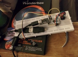
The goal of this article is to explain how you can easily communicate between an Android application and an arduino board.
It’s a good way to quickly prototype some stuff to connect some electronic to Internet!
Prerequisites
– You need to be able to write a simple program on your ardunio.
– You need to be able to write a simple application for android.
– You need an android phone that support USB OTG mode.
Please note that the code is not “clean”. My goal was just to create a simple demo.
You can download the code here: AndroidArduino.tar. My code is totally free to use if you remove any references to my name.
It’s not the only solution. You can implement a USB protocol on the device. Another way is to use an external serial module or some bluetooth adapters.
Shopping time!
Cost: ~$25 + mobile phone.
You can use your own stuff, but the samples work with the following material on DX.com. Please note that the average delivery time is 4-6 weeks. If you buy for less than $50, you don’t have to pay taxes in Switzerland.
Connect a USB cable to your phone
http://dx.com/p/micro-usb-on-the-go-host-otg-adapter-pair-50774
A USB to TTL port to communicate with arduino using USB port.
http://dx.com/p/ftdi-basic-breakout-arduino-usb-to-ttl-upload-tool-for-mwc-black-142041
Arduino Micro-Controller
http://dx.com/p/new-version-pro-mini-atmega328p-microcontroller-board-white-173878
A RGB LED controller
http://dx.com/p/keyes-5050-rgb-led-module-for-offical-arduino-products-red-silver-232073
A temperature sensor
http://dx.com/p/ds18b20-digital-temperature-sensor-module-for-arduino-55-125-c-135047
You may want to buy
Breadboard
http://dx.com/p/840-point-solderless-breadboard-118355
A nice kit
http://dx.com/p/arduno-37-in-1-sensor-module-kit-black-142834
Wires
http://dx.com/p/male-to-female-dupont-breadboard-jumper-wires-for-arduino-40-piece-pack-20cm-length-146935
Build the stuff
If you want to use my code sample:
Connect the RGB led:
* – Connect red to pin 5
* – Connect green to pin 6
* – Connect blue to pin 7
* – Connect V to VCC
Connect temperature sensor to:
* – S to pin 12
* – Middle pin to VCC
* – Pin “-” to GND
Connect the programmer to the device and burn my firmware. You should see a red, green and blue “lightshow”.
Connect the USB port to the OTG adapter.
Install my application on the phone, connect the device to the phone and you will be able to communicate between the phone and the arduino using the USB port of your phone and a serial protocol.
You can get the temperature of the device on your phone. You can set the level of the leds.
You will see the battery of the phone going down really fast 🙂 You can install a powered USB hub, but it doesn’t work on every phone.
On the Ardunio side
You need to include #include <HardwareSerial.h>
In setup(), set the speed of the serial port
void setup() {
Serial.begin(9600);
….
}
in loop()
int r = Serial.read();
if (r != -1) { <– If we have received something
if (r == ‘x’) { <– If we have received the char ‘x’.
…
}
}
Send some char back
Serial.print(“XXXX”);
It’s really easy to communicate using the serial port on the arduino part.
In “tools -> serial port” of the development kit, you can communicate with your device and test that you communication protocol is working as expected before testing on the phone.
On the Android side
You can see the documentation here:
developer.android.com/guide/topics/connectivity/usb/host.html
In my activity, I start the communication with the serial port.
private Ardunio ardunio;
arduino = new Arduino(this) {
“Arduino” is an abstract class in a thread. I instantiate the class and implement the abstract method in my activity.
@Override
public void info(final String txt) {
runOnUiThread(new Runnable() {
@Override
public void run() {
t.setText(txt);
}
});
}
};
In my Activity, I start / stop a thread that communicate with the Ardunio.
@Override
public void onPause() { super.onPause();
ardunio.shutdown();
}
@Override
protected void onResume() { super.onResume();
ardunio.start();
}
I use the library provided by FTDI to interact with the device. FTDI is the manufacturer of most popular USB<->Serial chips.
private final D2xxManager ftD2xx;
Open the first FTDI device
int cntDev = ftD2xx.createDeviceInfoList(activity);
if (cntDev >= 1) {
FT_Device dev = ftD2xx.openByIndex(activity, 0);
…..
dev.setBaudRate(9600);
Read what is on the serial port. Timeout after 0.2 seconds. Please note that I read one character at a time – the FTDI implementation seams to have a bug if you read more than one character at a time…
int c = 1;
while (c > 0) {
c = dev.read(b, 1, 200);
if (c > 0)
buff.append((char) b[0]);
}
I can send something to the serial port using
String s = “r” + this.r + “g” + this.g + “b”+ this.b;
dev.write(s.getBytes());
Don’t hesitate to see my code to understand the details and some “tips” that are not included in this article!
